Home >
Products >
Heavy Commercial Vehicle Engine Training Systems >
Engine Operation Testing Training Platform


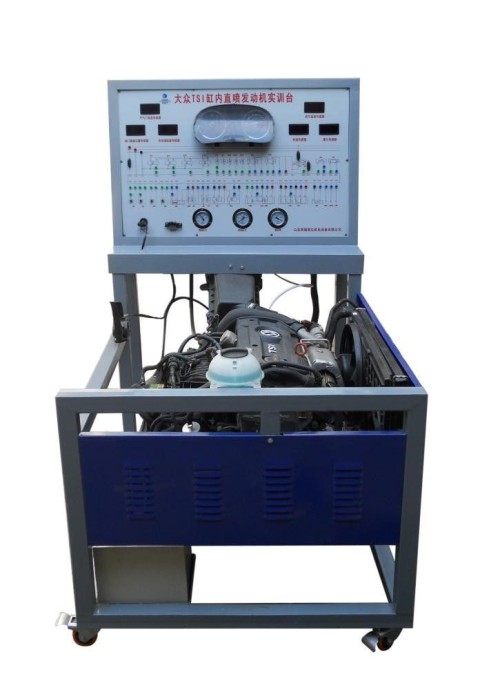
Engine Operation Testing Training Platform
Description:
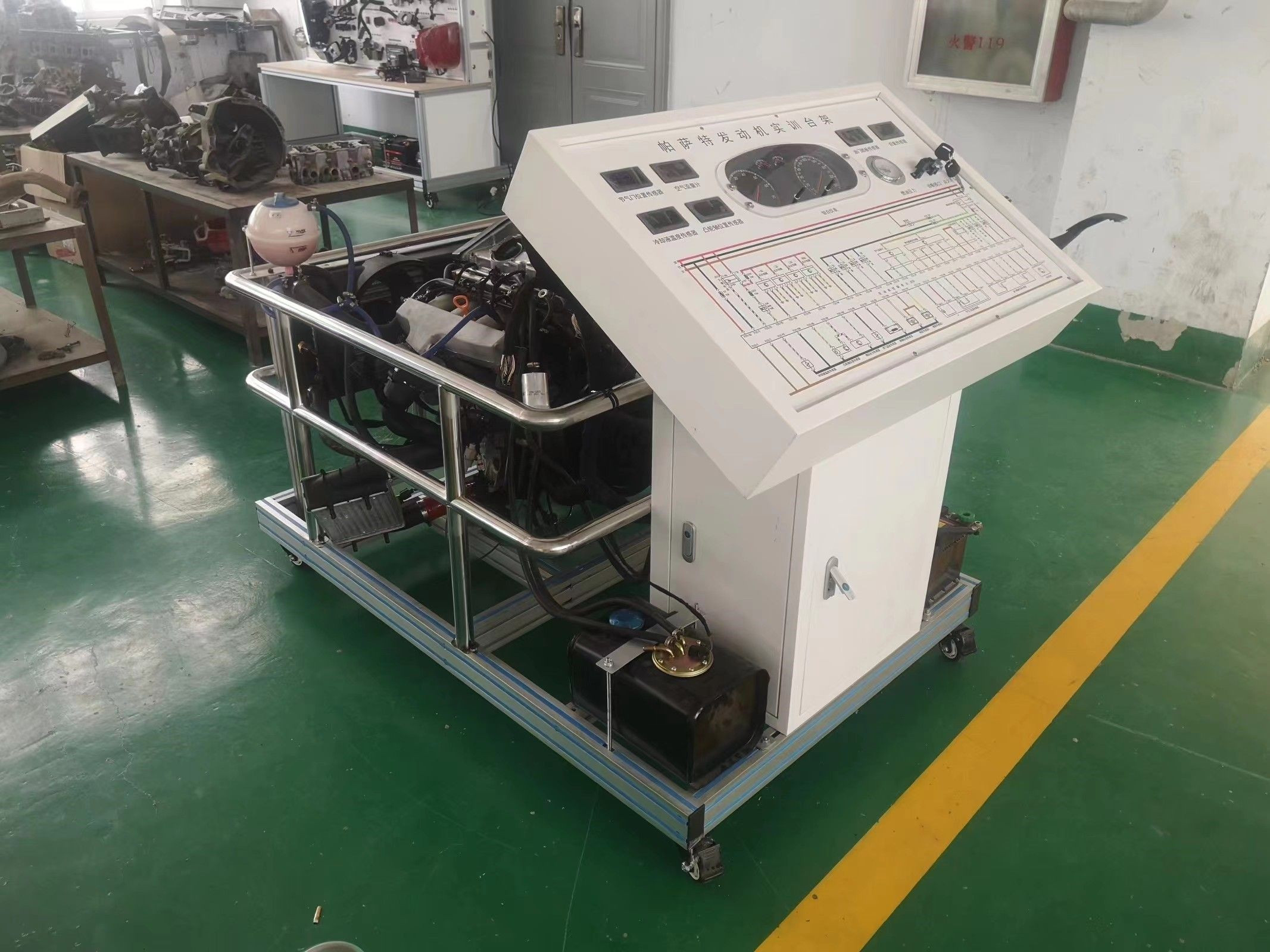
(1) Experimental bench:
It is composed of Volkswagen Santana 1.4L engine gasoline engine system assembly, all sensors, actuators, oil supply system, heat dissipation system, power supply system, intake and exhaust system, throttle control mechanism, etc.;
(2) Console:
The panel is equipped with a combination instrument, control computer ECU, ignition switch, fault diagnosis seat, intake vacuum pressure gauge, fuel pressure gauge, sensor parameter display and detection digital meter, fuel injection frequency LED display light;
Adjustable fault simulator; The panel is equipped with a color schematic diagram of the engine electronic control system circuit and an external computer detection terminal.
Second, the function of the equipment:
(1) Display function:
1. On the basis of the engine assembly, the related systems are arranged according to a reasonable position, and the structural composition and working principle of the automobile engine control system and related working accessories are intuitively displayed;
2. The color structure and circuit schematic diagram of the engine electronic control system are convenient for the teaching of the structure and principle of the overall engine electronic control system.
(2) Dynamic operation function:
On the basis of the engine assembly, it is equipped with various related auxiliary control systems, all sensors and actuators are complete and effective, and the engine runs normally, which is suitable for various working conditions of the engine.
(3) Real-time display function:
1. Instrument cluster (display engine speed, water temperature, fuel volume, oil pressure is too low, fault lamp, etc.);
2. Digital table (real-time display of the voltage value and change of each sensor parameter of the engine);
3. Pointer table (showing inlet vacuum, fuel pressure, oil pressure and other parameters);
4. Bright LED light (showing the working frequency of the injector).
(4) Detection function:
The external computer detection terminal can detect and analyze the signals of various sensors, actuators and electronic control units.
(5) Adjustable fault simulation function:
It can simulate the voltage parameters of the main sensors of each control system of the engine, and detect the change of the engine operating state caused by the change of the sensor input signal in real time.
(6) Diagnostic function:
Equipped with a special fault diagnosis seat (OBDII detection port), it can be connected to a special decoder to carry out fault code reading, fault code clearing, data reading, waveform analysis, execution component testing and other detection experiments on the engine electronic control system.
(7) The equipment is equipped with a fault setting system and can have 64 output channels. The 64 output channels can be configured individually, and can be configured into normal mode, delay mode, jog mode, cycle mode, and fixed duration mode through the standard ModBus-RTU communication protocol. The 64 output channel status can also be read and written via the standard ModBus-RTU communication protocol. It can be directly connected to the industrial control board, PLC, industrial control instrument, configuration screen or configuration software on site; A variety of output parameters are optional and customizable;
1. Support standard ModbusRTU protocol;
2. Address (1-255), baud rate (4800bps-115200bps);
3. Address, baud rate, restore default parameters, query parameters, can be set, modified, and saved after power-off; IWDG, WWDG double watchdog, never down, communication operation indicator, communication flashing;